
Spindle System – Encoder
At FISCHER USA, you can have full confidence that we will provide Swiss Quality with around the clock access to our team of over 60 people. We fully test all repaired high-speed spindles to ensure they operate at our facility in the same way that they will operate on your machine. Our team is well versed and knowledgeable about spindles and their many parts:
- Bearings
- Motors
- Shaft
- Clamping System
- Unclamping System
- Sensors
- Encoder
- Cooling System
- Sealing System/Requirements
The Encoder's main function is to provide a stable and accurate feedback of the shaft speed and position to the drive control. This is a necessary operation as it ensures:
- Closed loop operation
- Proper shaft orientation & positioning
- Ability to reach maximum torque from 0 RPM
- High power cutting and loading to maintain set speed with minimum slip loss
Encoders are often referred to as a Feedback Sensor, Speed Sensor, or Vector Control.
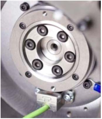
An encoder system, with the spindle, contains two components, gear wheel & read head. The gear wheel is a mechanical component that is directly attached to the rotating assembly, also known as the shaft. The read head houses electronics and has a direct connection to control. Both of these components are crucial for proper feedback to control.
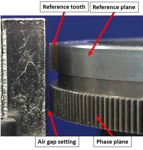
Gear wheels are made from ferrous metal. Ferrous metals including steel and pig iron (with a carbon content of a few percent) and alloys of iron with other metals, such as stainless steel. Two separate planes are machined into wheel; the Reference plane (single tooth) and Phase plane (many teeth). The number of teeth in phase plane will vary depending upon the diameter of the wheel, but typically the number of gear wheel teeth is either 128 or 256. The higher the number of teeth means the higher the positioning accuracy.
Gear wheels have an air gap that is set between pickup and rotating gear wheel. The finish of each tooth (reference & phase) is very imperative and any damage will cause defects in signal quality. Runout of the wheel is also very important to proper signal output, less than 0.02 mm is the typical runout spec.
The read head is constructed to be extremely compact. Read heads will also have a EMC (Electromagnetic compatibility) that is rated. Read heads consist of 2 magnets that are in separate planes. One magnet is for reference and one is for phase which has three output feedback signals:
- A phase
- B phase
- Reference
Read heads also have the following technology:
- Supplied with 5 volts
- Signals are a sine wave output (optimum waveform for electronic equipment)
- 1 volt peak to peak
- Have the capability to record operating hours in certain set speed ranges (histogram)
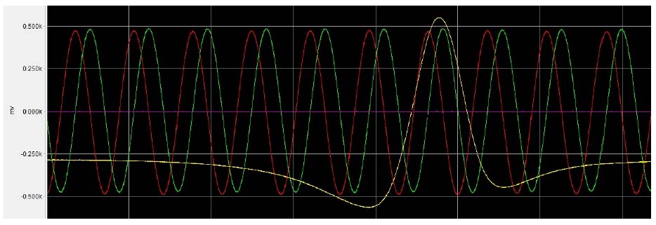
The following graph depicts encoder output signals:
- A + B signals operate in sine / cosine wave with 90° offset (Green & Red)
- Reference signal operates with single peak sine wave (1x per revolution - Yellow)
- This signal is most common in high speed spindles
- Analog signals are sent to control and typically converted to a digital signal
If you are experiencing any issues with your encoder component or any other system within your spindle, contact our knowledgeable team today!